


Stacking Ginlong or Power-One Aurora Wind Inverters
By: Rob Beckers
Both Power-One (ABB) and Ginlong make superb inverters for wind turbines, with a very wide MPPT Voltage range, and great efficiency. However, they top out at 5kW (Ginlong) and 6kW (Power-One) in inverter size. What to do if your wind turbine needs more than a 6kW inverter? The answer is to stack wind inverters, and you can stack as many inverters as you need to meet the power demands of the wind turbine in 5 or 6kW increments. This article explains in detail how to do so.
Wind inverters can be stacked by connecting them in parallel; they all receive power from the same source (the wind turbine) and they all contribute in sending power out to the grid. Since the objective is to create inverter power that exceeds that of the largest single inverter, typically multiple 6kW inverters are stacked.
Stacking Inverters – Electrical Diagram
Both the Ginlong and Power-One Aurora inverters are ‘transformerless’ inverters. This means they do not contain a transformer internally, to provide galvanic separation (for DC) between input and output. This is great for single inverters, since it does not incur the additional losses of a transformer (typically a few percent), and results in very high inverter efficiency. For stacking multiple inverters it creates a problem though; simply hooking them up in parallel would make them fight over DC levels on their inputs and inject DC current into the grid (a big no-no as far as the utilities are concerned). What is needed is an isolation transformer on the grid side, for all but one of the stacked inverters (i.e. 2 inverters = 1 transformer, 3 inverters = 2 transformers etc.). Here is a diagram that illustrates the concept:

Typically wind turbines supply 3-phase AC with variable voltage and frequency. This is converted to DC using a rectifier (either supplied by the wind turbine manufacturer, or a regular 3-phase bridge rectifier with a heat-sink, or Power-One’s Wind-Interface box). The inverters turn this into grid-quality AC. The isolation transformer keeps both inverters from fighting each other, and code requires an AC disconnect before back-feeding the power onto the grid. More inverters can be added as needed, each additional one will also need an isolation transformer.
The actual implementation has a few additional components, to comply with code, to make the installation safer, and to make the stacked inverters work more efficiently. Please take a look at our suggested wiring diagram. This example uses Power-One inverters, where the 3-phase AC coming from the wind turbine is rectified by two PVI-WIND-BOX’es. These are not needed if the turbine outputs DC or comes with its own rectifier. The DC output from the wind boxes is connected to the inverters’ inputs. The wind boxes also generate a frequency signal that the inverters can use for frequency-based MPPT. If the inverters are programmed for voltage-based MPPT then the frequency wires are not needed, and Ginlong wind inverters do not have a frequency signal input. The slave inverter has the isolation transformer to provide galvanic separation for the input of that inverter, so it can be paralleled with the other inverter. The AC power from the inverters backfeeds a number of dual-30A breakers in a small sub-panel, where it is combined and continues on to backfeed a dual-breaker in the main panel.
There are some refinements that make this setup work more efficiently. There is no need to keep the isolation transformer running when there is no wind (which can be a significant percentage of time). Normally we would use the master inverter’s ‘alarm’ output to switch a contactor in the transformer’s AC connection to disconnect it when not needed (by programming the master inverter to provide a signal on the ‘alarm’ output when it is in production mode). However, a bug in the Power-One inverter prevents this from working properly; for reasons as yet unknown the master inverter will indefinitely stay in production mode when it is stacked together with more inverters (it will work fine in single-inverter configuration). To work around this bug the Omron voltage measurement relay is added. It measures one phase of the wind turbine’s AC voltage, and when that falls below approximately 55V for more than 30 seconds the Omron relay will disengage the two LC1D32G7 contactors. This will power off both inverters and the isolation transformer during periods of very little or no wind. The Omron relay needs to be set up so its ‘undervoltage’ sensing on AL2 is set to its minimum value (10%), and the delay time is set to its maximum (30 seconds).
The circuitry with the Omron measurement relay and contactors can be left out for windy sites, where the inverters would spend very little time switched off. Of course, if the added complexity is deemed unneeded that in itself can be a reason to leave this part out. It’s not needed to stack the inverters, it is drawn in the diagram for those that want a way to prevent idle losses.
The Delta surge arresters are there to provide a minimum of lightning and surge protection. They are far from foolproof, however, they do provide a real measure of protection for very little money. The two arrestors on the wind turbine’s AC side work in tandem: There is one arrestor at the foot of the tower, with the turbine’s stop switch. This takes care of shorting the very large surges of near or direct lightning strikes to ground. The second arrestor close to the wind boxes, connected to the terminal block, works with the impedance formed by the lengthy wiring between turbine and inverters to short what is left on the lines to ground. The third arrestor is placed on the grid side of the inverters, mounted on the sub-panel, to short grid-induced surges to ground.
Each Power-One inverter can be programmed to output up to 6.4kW of power, so two inverters are good for 12.8kW output power to the grid. If more power is needed, for a larger wind turbine, the same principle as shown in the wiring diagram can be extended by adding components: For 18.6kW output power another PVI-WIND-BOX, PVI-6000 inverter, isolation transformer, and LC1D32G7 contactor are needed. Of course, the other components need to be scaled to handle the additional current (another dual-30A breaker in the sub-panel, a larger stop-switch, a larger AC disconnect, and a larger dual-breaker in the main panel).
There is one important note you should be aware off: Transformerless inverters have very strict ground-fault detection build into them (as required by the UL and CSA norms). When the inverter is placed behind an isolation transformer this mechanism will not work properly, and erroneously indicate a ground fault. This will happen to the slave inverter in the wiring diagram, behind the isolation transformer. For that reason it is necessary to switch off the ‘Riso Measurement’ option inside the inverter. This is done through the ‘Advanced’ menu choice of the AuroraInstaller program and involves an inverter-specific access code. If you are planning to use inverters in a stacked configuration please let us know, we can generate the inverter-specific code for you, and help you program the inverter properly.
Important Note – Overcurrent Protection
If you use your own rectifier or controller (as opposed to the PVI-WIND-BOXes), make sure there is an overcurrent protection device in the form of a DC rated fuse or breaker in the DC path of each inverter. While this is common sense, surprisingly few third-party controllers contain overcurrent protection, or if they have it will be rated for the aggregate current of all the stacked inverters. If the rectifier fails it will send AC into the inverters. The inverter has some protection for AC on its input, by using a diode that will short-circuit the input if the polarity is wrong. That diode will only handle a limited current though before it blows, and when it does, that is the end of the inverter. Size the overcurrent protection such that regular use will not exceed 75% of the fuse or breaker rated value.
Stacking Inverters – Mechanical Layout
There are of course many ways the inverters can be nailed to the wall, and they will likely all work fine. However, to help you with planning, and to illustrate some of the practicalities we have a suggested layout using Power-One components, with dimensions in inches, as shown below:

The wind boxes are offset from the inverters so their heatsinks are not obstructed, which helps in their cooling. For that same reason there needs to be a minimum of 6 inches of clearance between the inverters and the ceiling. We have found 3/4″ plywood to work well in providing a surface for fastening all the components to (do not use OSB; it does not have much holding power for screws). The PVC junction box is there to hold the Omron relay and contactors (mounted on a little strip of DIN-rail). If more space is needed for mounting items, simply add one or more of the same 12″x12″ PVC boxes above each other (below the sub-panel). They work very well for this purpose and meet electrical code.
To interconnect all the components we have found flexible (gray) conduit to work great, it is also known in the trade as ‘liquidtight’; it is very fast to install, and well, flexible. We do suggest to use a layout that allows for at least 10″ between components. Shorter pieces of flex conduit are hard to work with if any amount of bending is needed (it is fine if items are connected by a straight piece of conduit, such as two PVC boxes mounted right above each other). For an indoors installation you can throw away the rubber gaskets contained in the flex-connectors, this makes it easier to flush-mount them to the boxes. Except for the wind boxes, we suggest using 1″ inside diameter conduit to have sufficient space for all the wires and be code compliant. Each inverter has two knock-outs of this size at their bottom (and several more on the sides). The wind boxes come with two 3/4″ knock-outs already open, and it is easiest to connect them using two pieces of 3/4″ flex conduit; one can be used for the AC wiring from the wind turbine, the other for DC wiring to the inverter and the frequency signal lines if there are any. For a neat installation the conduit routes to a common wiring tray. The transformer is best left on the floor, it is very heavy. Just secure it to the back wall so it cannot move around. This layout can be extended very easily in case more inverters and transformers are needed by repeating it to the left side.
The sub-panel can be connected to the main load center by using the proper gauge NMB cable (such as 6 AWG Romex for a dual-inverter setup). Typically this has to go out to the AC disconnect switch first, which is generally required to be mounted close to the electrical meter by code, and then back in to the main panel. For the interconnections between components it is easier to use individual wires of the proper gauge (mostly 10 AGW for the wind boxes and inverter, and 18 AGW for control wiring). It can be difficult to connect the frequency wires in the wind boxes; to make this easier first take the three spade-connectors off the small printed circuit board that is in the way (you will see what we mean). Of course, do not forget to reconnect them again in their proper place! Use crimp-on eye connectors for the ground wires in the inverters and wind boxes; they can then simply be fastened under the ground bolts that are already there. You will also need ground-bars for the junction box(es) and wiring tray, just fasten them in there at a place that is convenient.
Here are some detail pictures of an actual installation:

Stacked dual-inverter installation for Bergey 10kW Excel 10kW wind turbine

Breaker/combiner panel for combining two inverters

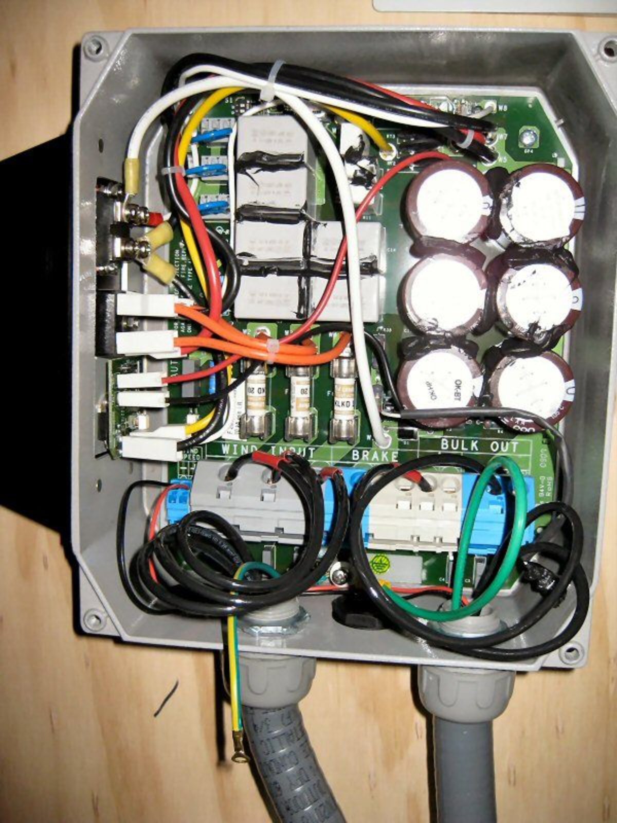
Power-One PVI-Wind-Interface rectifier box
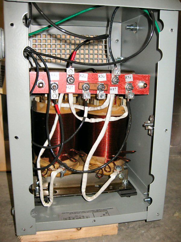
7.5kVA Isolation transformer

Omron Voltage-sensing relay and contactor
