


Wiring for Lightning
By: Rob Beckers
What we want to discuss in this section is how to wire up a wind turbine so lightning has as little chance as possible to do damage. As with proper grounding, here too there are right and wrong ways of getting the job done. We will work our way down from the tower, to the inverter or charge controller, and to the rest of the house.
The wires that come down the tower should be either in metallic conduit (EMT), or if you are lucky enough to have a tubular-type tower they should run inside the tube. The reason is once again skin-effect: The bulk of the energy from a lightning strike will want to travel on the outside of the metal conduit, keeping the energy that couples into the wiring to a minimum. In essence, the metal conduit forms a Faraday cage. In case of a tubular tower, do not forget to provide strain relief for the wires at the tower top. There are neat Chinese-finger-trap like devices for this purpose that envelope the cable (known as “Kellems grips”, named after the brand name that makes them).
The current involved in a lightning strike and the inductance of the tower can quite easily set up an instantaneous voltage difference between the tower top and bottom of 100 kV (100,000 Volt). That means every foot of a 100 feet tower can have a potential difference of 1 kV, and by having the turbine power wires come off the tower at 3 feet height we just created a 3 kV voltage difference between those wires and ground. That can be minimized by routing the turbine wires all the way down to the ground (or into the ground), and from there to their destination. Even if there is a turbine disconnect near the tower, it is advisable to run the wires underground to a separate pedestal with the disconnect, and from there back again underground onward to the house.
Running the turbine wires underground to the inverter or charge controller will greatly help to lower the energy traveling down those wires. Unfortunately running the wires underground is not going to prevent lightning from coupling in completely. The large amount of energy in the lower frequencies involved in the electromagnetic field of lightning can penetrate quite deeply into the ground. Any wires running in the ground will act as a transformer, coupling in that energy. That is how a nearby lightning strike can also couple into well-pump wiring and destroy the pump, pressure switch, and quite possibly also all the electronics hooked up to the house grid. A surge arrestor will have to deal with that energy further down the line.
If possible, the grounding wire that connects the tower ground system with the building perimeter ground should be kept at least 3 feet away from the turbine power and signal wires. This is for the same reason as mentioned above: Parallel wires will act as a transformer and during a lightning strike a large current will flow in that ground wire. Keeping them separate will cause less energy to couple into the power or signalling wires.
Usually a wind turbine is placed some distance from the house. For once, we get something for nothing here; Having at least 50 feet of wire creates a high impedance (resistance) for much of the energy of a lightning strike and keeps it from traveling down the line. It also helps to make any surge arrestor devices placed around the inverter or charge controller to be more effective. The inverse of this is also true: If you place an equipment shack with electronics at the foot of the tower you are going to have a much harder time in preventing lightning damage.
Lightning or surge energy does it dirty work (the damage to equipment, especially electronics) because it creates voltage differences between the various wires. There can be a voltage difference between the phase wires of the wind turbine’s alternator, or between the phase wires and ground. Maybe the grid wires and the turbine’s phase wires have a (large) voltage difference. Also entirely possible and much more insidious is a voltage difference between the various ground wires (the inverter ground and the turbine ground, or the grid ground and the turbine ground). Those voltage differences can be very large, thousands of Volt, and modern electronics do not take kindly to anything over their maximum rated voltage. In the case of lightning, these voltage differences can create very large currents, thousands of Ampere in magnitude. Clearly not a good thing either. The professionals have a fool-proof answer to this; the single-point ground.
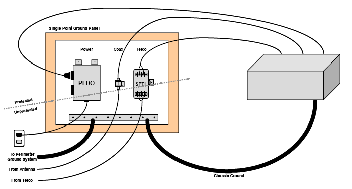
A single-point ground means that all wires are physically routed to a ground bus. They come in on one side, and exit on the other (sometimes that can be ‘through’ the ground bus from one side to the other, sometimes that means cables enter on the bottom and exit on top). All different ground connections, such as the house or grid ground, wind turbine ground, photovoltaic ground etc. connect to this ground bus. This would also be the place where surge arrestors are located that keep the voltages of all other wires (turbine phase wires, grid wires, and also signal wires like telephone and Internet wires) tied closely to the ground voltage. The surge arrestors literally straddle the ground bar, making for a ‘protected’ and an ‘unprotected’ side on the ground bar. The equipment itself is only grounded through a single connection to this ground bus, on the protected side, and it is installed in a way that insulates it from other conductors (such as the concrete floor, since concrete is a conductor, or the walls). The image above shows the concept. While the images in this section are from HAM and broadcast use, it works exactly the same way for wind turbines and inverters.
 The effect of a single-point ground is that the actual voltage of the equipment, including the equipment ground, can float up and down. Even if this is thousands of Volt in comparison to, for example, the floor. As long as there is no voltage difference between the various wires of the equipment, or the equipment pieces (such as an inverter and charge controller), there will not be enough voltage or large equalization currents to cause damage to the electronics. A single-point ground is very effective. It is how a broadcast station handles direct lightning strikes, over and over, without any damage. In the literature you will find another term, bulk-head entrance, that has a very similar meaning to single-point ground.
Most of us have to contend with an existing situation where the house is grounded on one side, the wind turbine wiring comes in on the other side, and an inverter goes somewhere in between. There may also be other equipment, not only RE related (batteries, charge controllers), but items like a stereo, television, or home-theater. The average household contains lots of electronics these days. This makes it impossible to follow the above principle of a single-point ground strictly. However, it is often possible to create multiple single-point grounds on a local scale, and couple that with strategically placed surge arrestors to provide a real level of surge and lightning protection.
For each of these single-point ground ‘islands’, do practice the principle of a ‘dirty’ and a ‘clean’ side for surge arrestors. Just as described above. It is what the professionals do, and it truly works. Keep the protected lines away from the unprotected ones, including the ground wires. When it comes to ground wires, try to keep them some distance away from the the power and signal wires, to avoid coupling in surges, even on the clean side of the surge arrestors. Short and direct ground wiring is best, turns should be gentle. Keep in mind that for a lightning-generated surge the ground wire can add several hundred Volt of potential difference for every foot of wire.
| Go to next: Effective lightning/surge arrestors |